
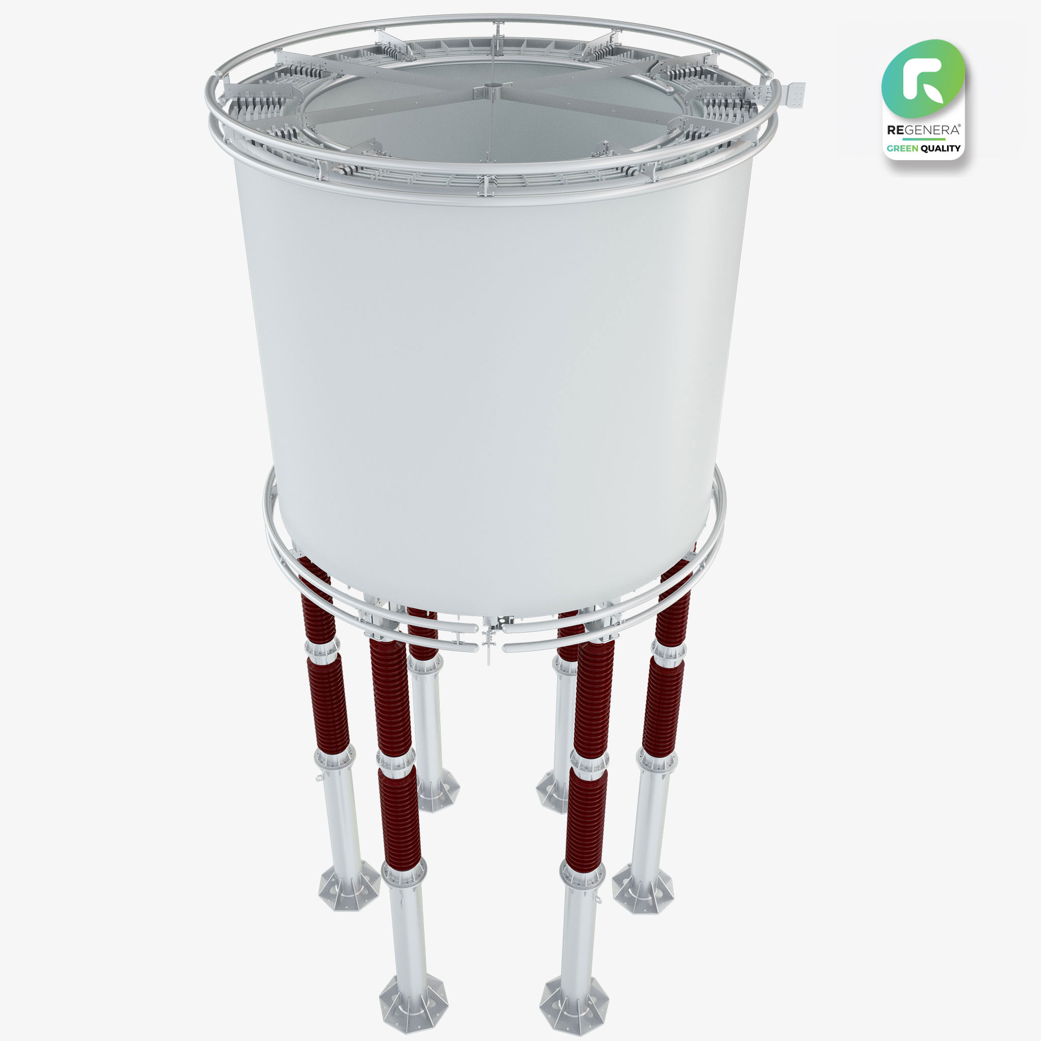
ACR for HVDC
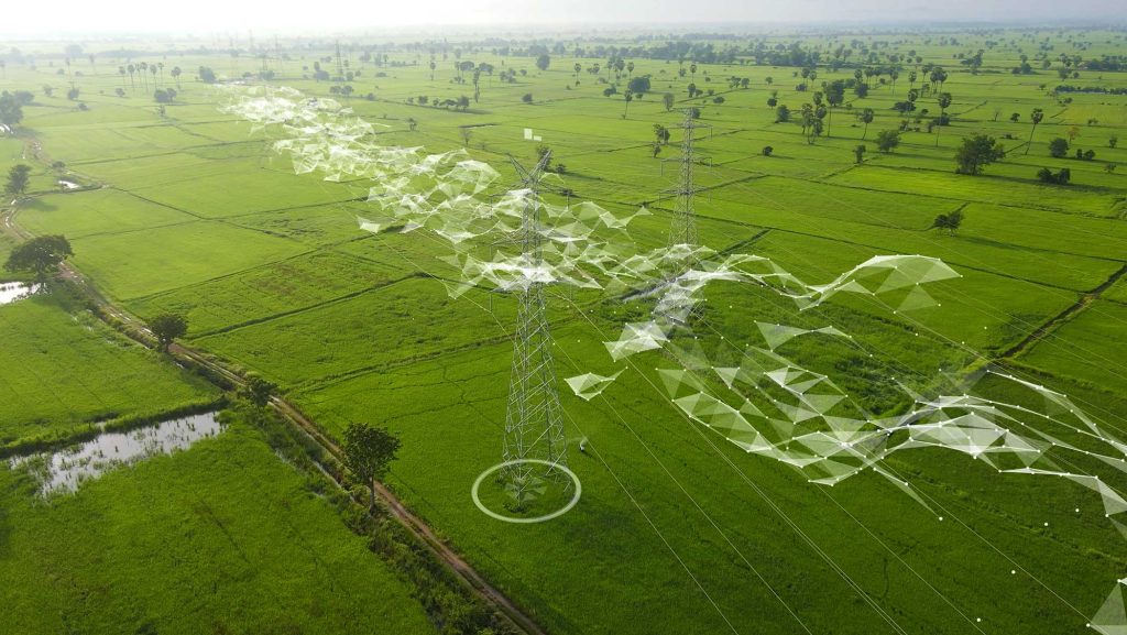
AIR CORE REACTORS FOR HVDC Unleashing a new level of safety and reliability Unleashing a…
ACR for Power Quality and Facts
AIR CORE REACTORS FOR POWER QUALITY AND FACTS Unleashing a new level of safety and…
Line Traps
AIR LINE TRAPS Unleashing a new level of safety and reliability Unleashing a new levelof…
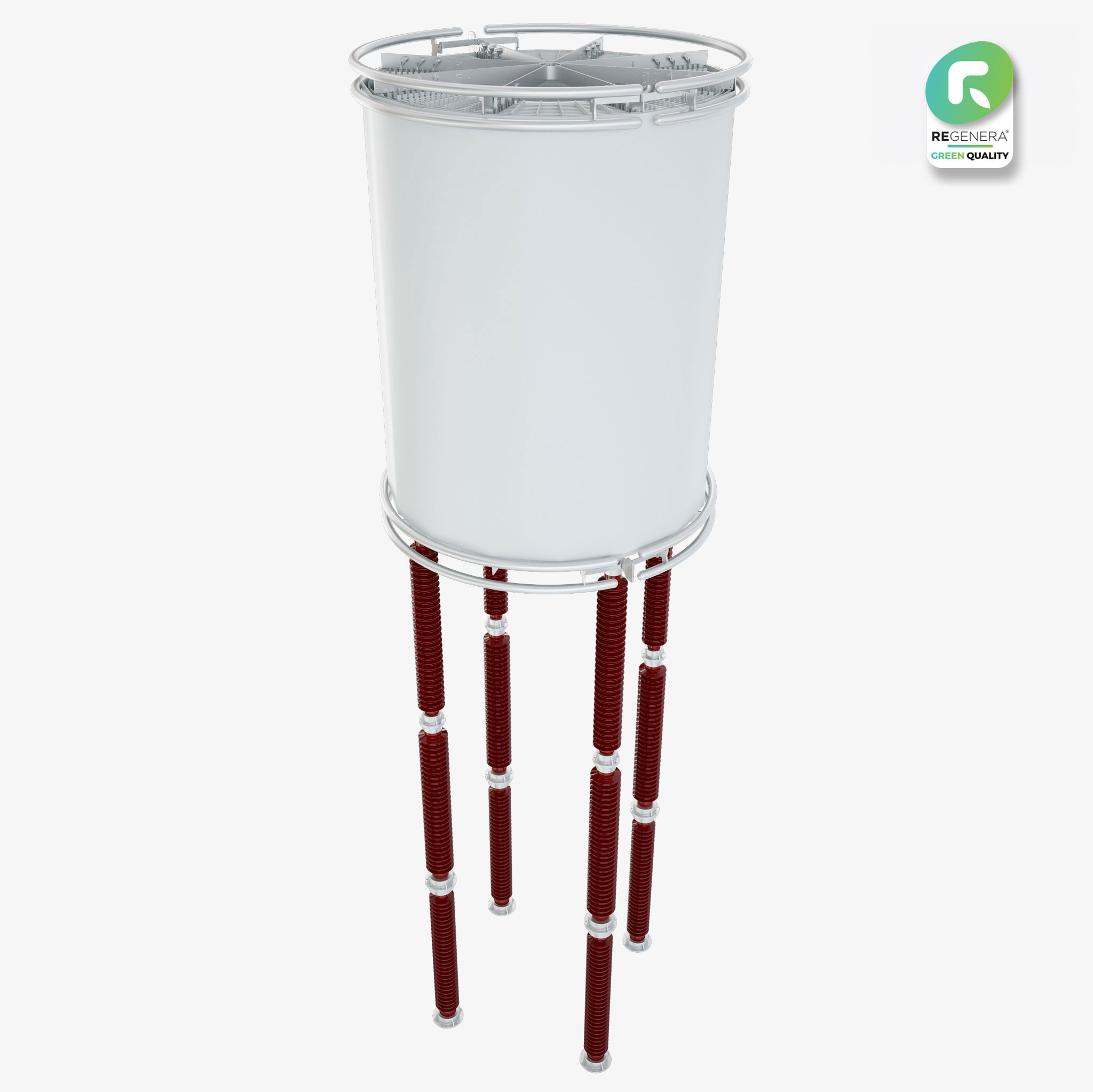
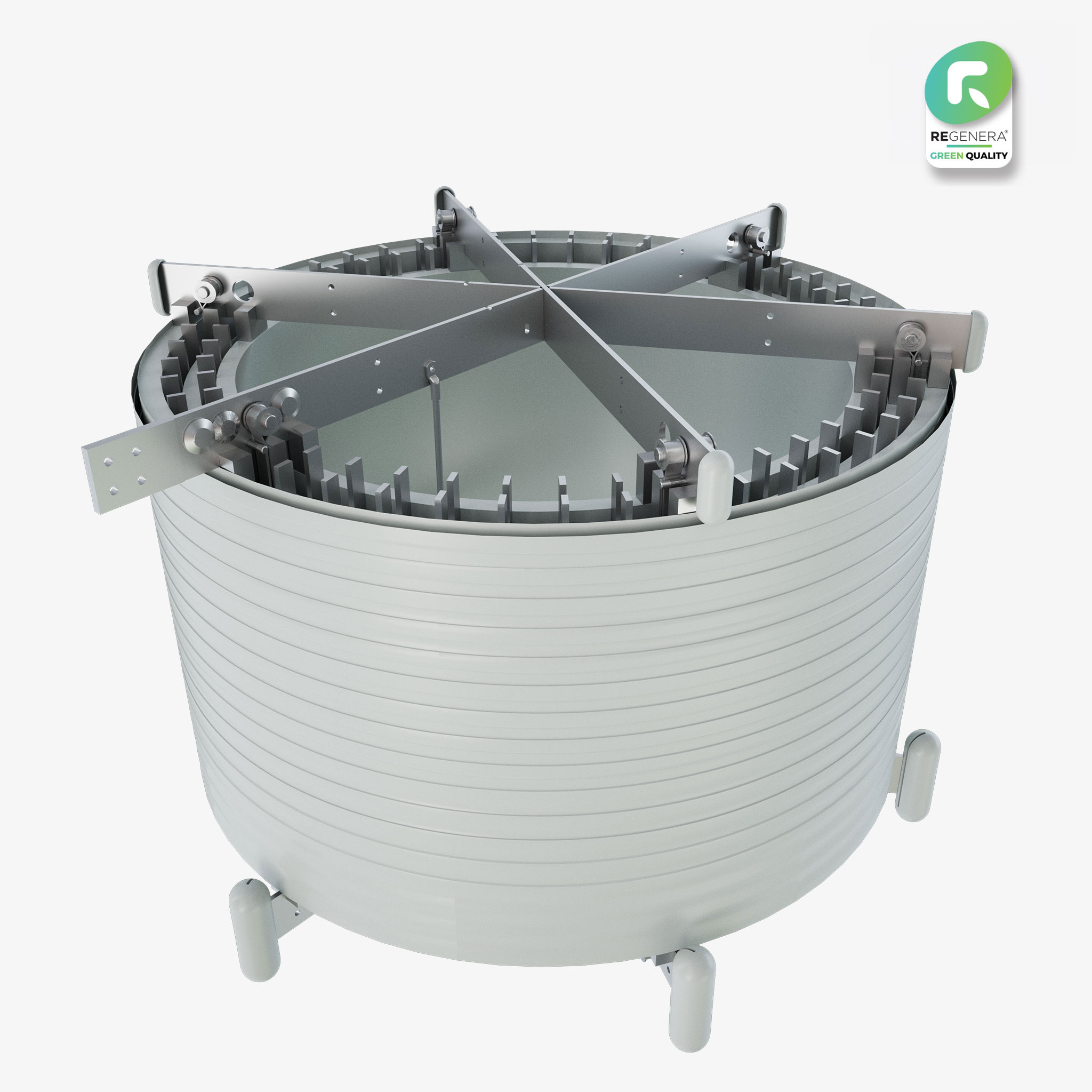
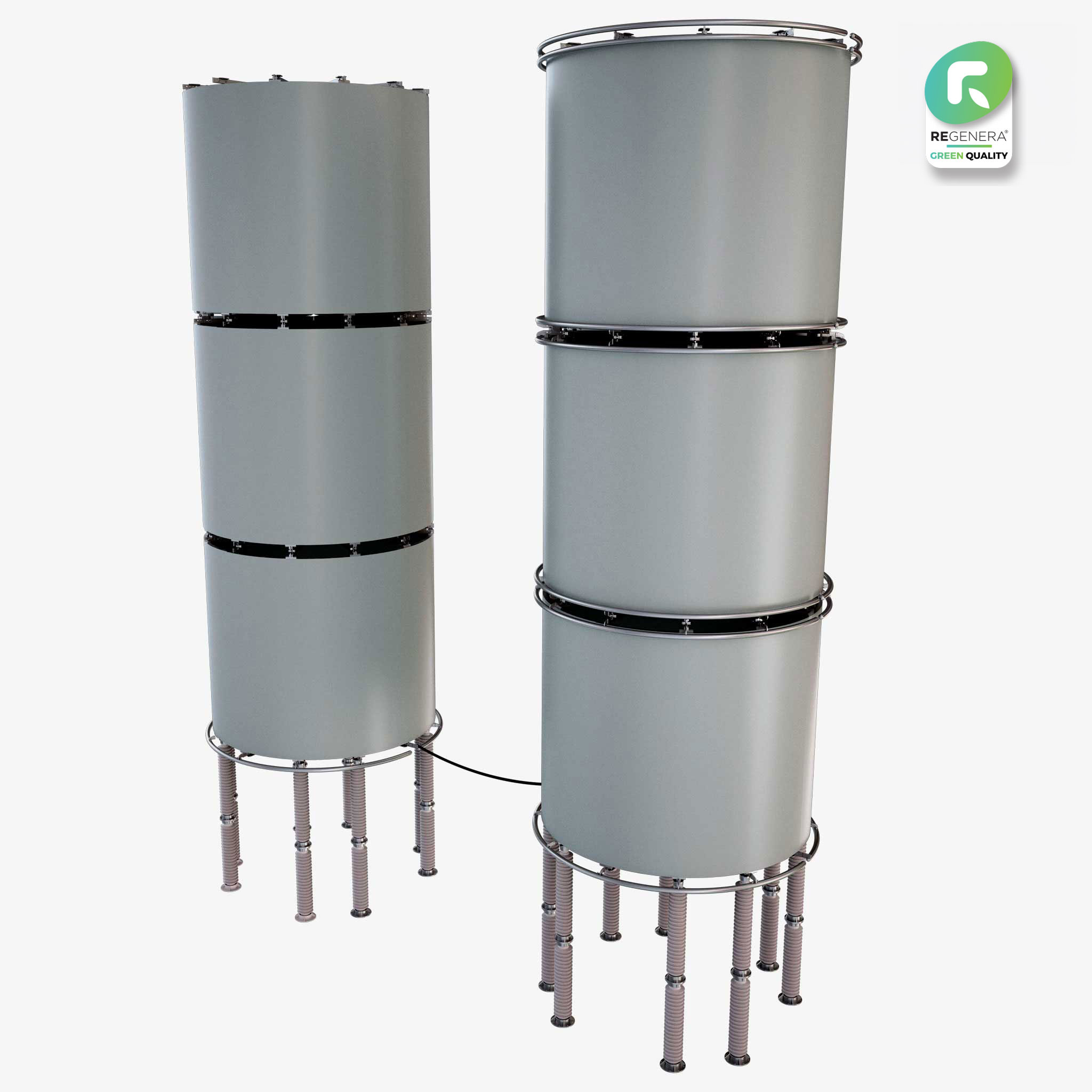
Air Core Series Reactors
AIR CORE SERIES REACTORS Unleashing a new level of safety and reliability Unleashing a new…
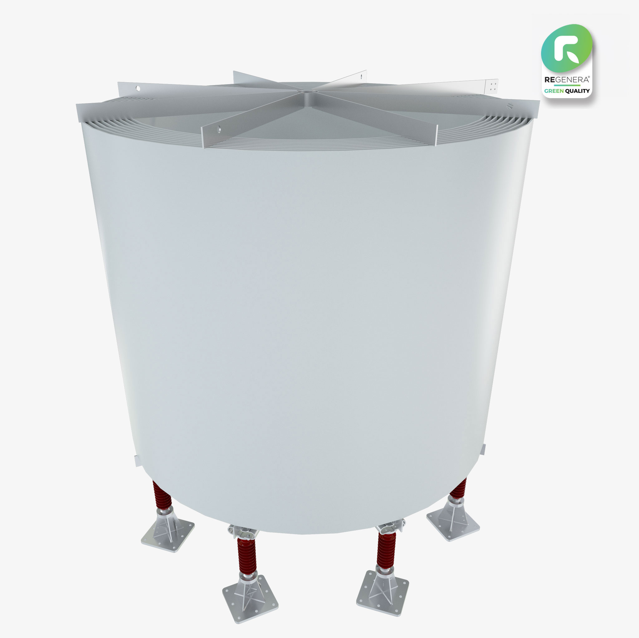
Air Core Shunt Reactors
AIR CORE SHUNT REACTORS Unleashing a new level of safety and reliability Unleashing a new…